

Engineering work
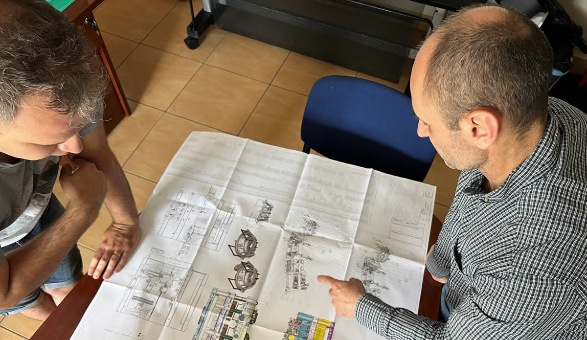
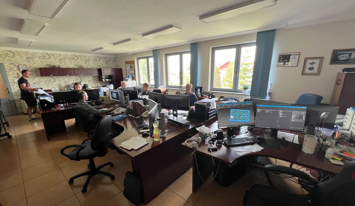
Engineering at PLASTIC-FORM Ltd. is based on CAD files or unique technical specifications provided by the Customer. Before starting the tool design we ask our partner to provide the necessary basic data (for example: 3D part data, 2D part drawing, plastic resin datasheet, injection moulding machine datasheet, production conditions). Qualified, experienced professionals generate the optimum design using integrated CAD systems (CREO and UNIGRAPICS).
According to the drawings and data we prepare the part feasibility, we analyze the moldability regarding the shape of part, as well as producibility regarding the technology. For this reason we make injection moulding simulation (with Moldex3D software), which helps us to simulate injection moulding process, to optimize product designing, and increase manufacturability. Using of the Moldex3D software helps the customer to analyze and appraise the product and tool design, which supports the technology, therefore the tool trials and problems can be reduced. With injection moulding simulation we can save money, time and energy for our customers.
At the end of feasibility - if necessary - attached our suggestions (DFM report) we ask modifications from our customer. After positive result of feasibility our engineers will start to design the tool.
The final tool design will be completely analyzed by simulation software, to bring the expected result. After finalizing, our milling centers and professionals takes over the tool making process, and making physical form of the tool designed by our engineers.
The engineering process will not be finished with tool design. The process will be followed by the engineers due the production and at the end of production with 3D scanning. After proto production the plastic part – if the customer requires – can be fully
3D digitalized, to compare with the original CAD model. In case of any difference our engineers are consulting with the customer, approving the modification, and making the necessary modifications on the tool. This kind of deviation
could be arising from deformation, or modification requested by the customer or product development, recommended by us.
3D scanning, Reverse Engineering
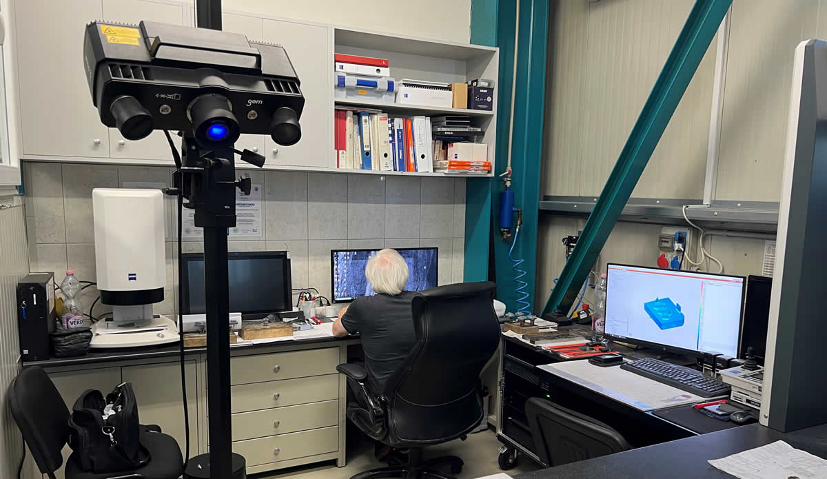
When the product or industrial parts (metal parts, tools and moulds, prototypes, injection moulded and casted parts) needs 3D model, our engineers can use the GOM ATOS 3D scanner to generate the part data which can be used for CAD/CAM purposes. After the reverse engineering the model will be represented by a 3D CAD data with the surface geometrical errors in a high resolution dense point cloud or polygon mesh surface (.stl file). Optionally surface or solid CAD model can also be available. All dimensions automatically will be transformed into a common coordinate system. Due the process the model can be redesigned, the shape can be modified (ideal method for scanning of broken, worn, damaged tools and for reproduction). It is possible to export the model in common standard formats, like .iges, .step or in special cases in feature and history based parametrical native formats, like SolidWorks .sldprt, Creo (Pro/E) .prt, Siemens-UGS NX .prt file. In most cases the .iges file is perfect for importing and editing in any CAD/CAM system.
With this high-end optical 3D scanner the forms 3D precise and accurate digitalizing can be done. The object can be any material including glass. Shiny objects will be temporary covered by a very thin layer of white powder for the period of scanning process, to obtain better scan quality. It is possible to scan huge objects with the help of reference points.
The ATOS 3D scanner is precise and cost-effective solution for many application areas:
- Quality control, quality analyzing
- Measuring
- Reverse Engineering
- Rapid prototype production
- Rapid milling
- Digital modelling
